Overview
As mentioned in the introduction, this wordclock is based on the Bernd Krolla implementation of the original QLOCKTWO. Krolla’s wordclock runs on a Raspberry Pi. I was searching for the most affordable implementation of a wordclock, therefore I ended up with a minimum of electrical components. The ESP8266 microcontroller is mostly shipped with firmware to run Arduino language. However, it also runs a port of Micropython which works great for this type of project.
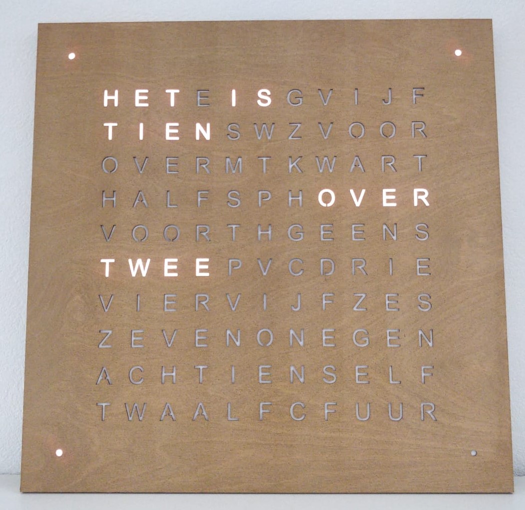
To show the time in words, a led strip is placed behind a laser cut matrix of characters. The hardware can be divided in woodwork and electrical components. After some iterations I ended up with a wooden frame made out of laser cut slats that make sure if a led lights up, adjacent characters will not be illuminated.
The electrical components consist of a ESP8266 NodeMCU microcontroller, DS3231 Real Time Clock to remember the time (the ESP8266’s internal clock is not reliable), TSL2561 luminocity sensor to adjust the brightness of the clock to the ambient light. Three small push buttons take care of setting the time and adjusting the color of the leds. A 5v DC power supply of 2A should be sufficient but I use a 3A version to be sure. The leds used are a WS2812B adressable led strip, in which each led can be controlled separately. The components are wired together with electrical wire and led strip connectors (to save a lot of soldering). Due to a maximum of laser cutting, it takes me less than 5 hours to assebmle a clock.
- width:
400
- alt:
Wordclock
Normal operation
When the power adapter is plugged in, the ESP8266 will boot in about 5 seconds. When it is the first power up, the clock shows the time since putting the battery in the RTC. To change the time, hold the OK (middle) button until “HET IS” flashes 3 times. The clock wil enter time setting mode, which is a 4 step proces elaborated in tools.py (function set_time()).
Set the time in hours using de back and forward button. When the correct hour is selected, push the OK button, the time in hours will flash.
Set the time in 5 minutes using the back and forward button. When the correct time (rounded down to 5 minutes) is selected, push the OK button, the time will flash.
Set the exact time for the minute leds using the back and forward button. When the correct time is selected, push the OK button, “HET IS” and the minute leds will flash.
You now can change the yellow value of the clock using the back and forward button. At default the led color in RGB is 255,255,50 but you can change the 50 to the desired type of white to yellow. Push the OK button when ready. The clock wil turn off for 2 seconds and then show the time in the new color.
When you pull the plug of the power supply, the RTC will keep track of the time using the CR2032 battery. Once power is restored, the correct time should show up.
To compensate for daylight saving time, push the back or forward button once to change the current time by one hour.
Shopping list
Electrical components (total about €50):
ESP8266 (NodeMCU) microcontroller
DS3231 real time clock (RTC)
TSL2561 luminosity sensor
SN74AHCT125N (or similar) logic level shifter
3A 5V DC power supply
Ledstrip with 114 WS2812B leds (30 leds/m)
13 led strip connectors
1 female DC plug
3 small push buttons
1 300-500 Ohm resistor
Electrical wire (22 to 24 AWG)
Woodwork (total about €50 to €80):
Laser cut front plate of 450x450mm
Interior matrix made out of laser cut slats
Slats for the border (could also be laser cut if desired)
4 small blocks to fixate screw on back plate
Back plate (+- 440x440x4mm, for example plywood)