Hardware setup
Woodwork
The front of the wordclock shows a matrix of 11x10 characters and 4 dots for indicating the minutes. Behind the characters, regular printing paper takes care of diffusing the light from the leds. Due to the required level of detail, I ordered a laser cut front plate from plywood. The dimensions are 450x450 millimiters. I use a thickness of 2 millimiters to ensure that a wide viewing angle on the clock is possible. See a template in the downloads section.
At the back of the front plate, a raster of slats hold the led strips in place. For a prototype I sawed these slats by hand, but a laser cut is a lot more precise and easier (3mm MDF). See a template in the downloads section. The raster has a height of 18mm. In a prototype I used a height of 15mm, but when de leds are placed 15mm behind the front plate, the middle of a character is a bit more bright than the edges. Therefore I use 18mm height now. The slats in the laser cut template are numbered from 1 (top) to 11 (bottom).
For the outside border I use slats plywood of 4mm thickness. The lengths are 450mm for the left and right side, 450-2x4=442mm for the bottom and 2 times 191mm for the top. In the middle a open space is present for the 3 buttons. The template for the interior matrix contains parts for holding the buttons which can be glued under this cutout. The outside border should be as high as the height of the raster (for example 18mm) + few millimeters for the led strips and tape + the thickness of the back plate (for example 4mm). Total height should be about 24mm in my example.
The back plate consists of a plywood plate of 440x440x4 millimeters with some cut outs and holes in it.
Steps for creating the woodwork:
Paint or varnish the front plate and border slats in a color or varnish of your choice.
Cover the backside of the front plate with paper. You can fixate it with regular tape. See picture 1.
Put together the matrix of slats for the interior and glue it to the back of the front plate. See picture 2 and 3.
Put together the pieces for the minute-leds. Glue them to the back of the front plate. See picture 2.
Solder all electrical components and mount them in the woodwork, see chapter electrical setup. The template for the buttons can be used to hold them in place and glue them to the front plate when alle electrical components are ready to mount.
Glue the 4 blocks to the front plate for screwing the back plate to the frame. See picture 4.
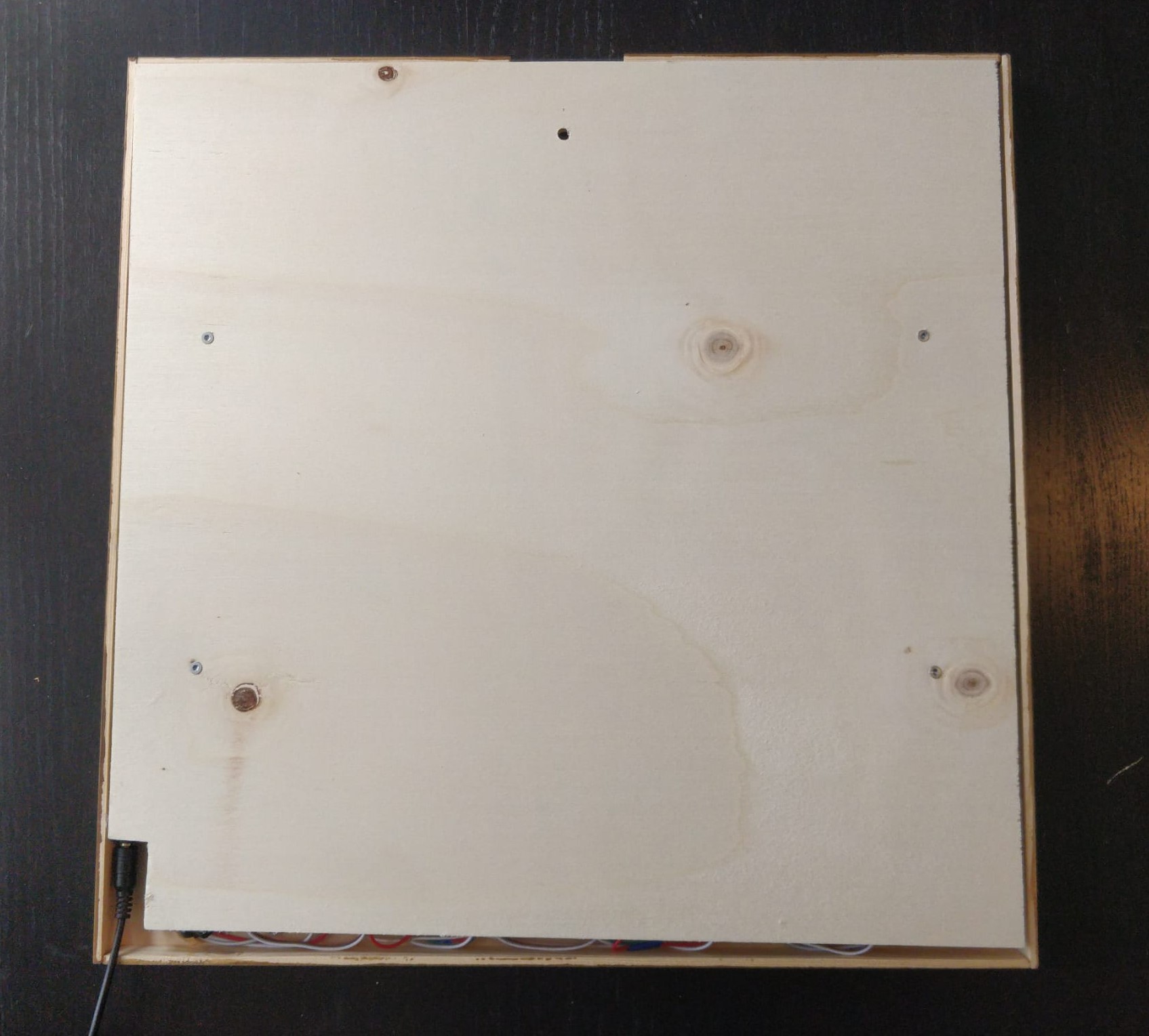
Place the back plate. Make sure you have a cutout for the DC socket, 4 screwholes for screwing the back plate to the glued blocks and 1 hole for hanging the clock to a wall. See picture 5.
Electrical setup
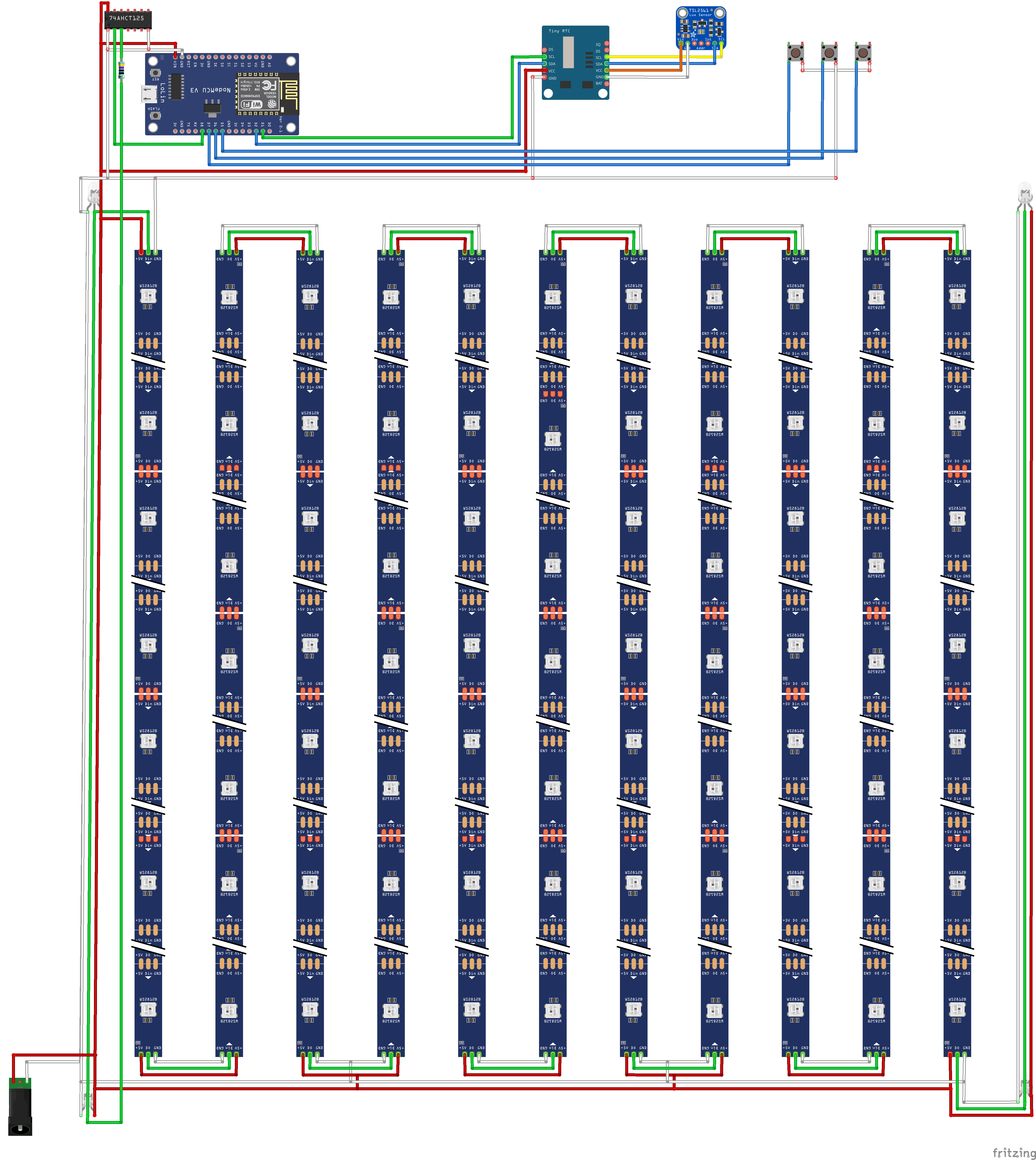
The fritzing scheme (picture 7) provides an overview how to solder the components. It is most easy to separate the power circuit, led strip connectors and wires for communication.
Power circuit: It is important to understand that the led strip has contunious circuits for +5v, ground an data transfer. A WS2812B led can draw up to 60mA, which can add up to quite some current. Due to the small wire gauge in the led strip the resistance will grow and cause voltage drop. The leds at the end of the strip will be dimmer than at the beginning. This can be prevented by sourcing power to the led strip at multiple points.
The 5v power is sourced by the power supply through the female DC plug. After the plug the power wires split into a circuit to the bottom for sourcing the led strip at multiple points. The +5v and ground for the led strip do not have to be continious, the data wire should be.
The other circuit feeds both leds on the left side (seen from the back) and provide the microcontroller, RTC en luminocity sensor with 5v DC. Also the buttons need to be connected to ground on one side. The microcontroller can be sourced by a micro USB plug (with 5v and ground soldered to the wires) or you can use the Vin- and a ground pin. The breakout boards (RTC and luminosity sensor) can also be sourced direct from the power circuit. Some RTC provide soldering points to daisy chain the wires (SCL and SDA for the I2C bus, 5v and ground). You could use a 3v3 output from the microcontroller to source the RTC, if desired. A TSL2561 requires 5v to function properly.
Led strip connectors: I use 3 pin ledstrip connectors to easily connect led strips to each other without soldering (for example https://nl.aliexpress.com/item/32966732241.html). To connect the minute leds in the left and right corners, I extended the wires of a led strip connector. Further, connector wire together adjacent led strips. On the bottom, on 3 locations the 5v and groud wires are stripped to solder the power wires to avoid voltage drop.
Data circuit: From the microcontroller, several data wires run to the components. I recommend to solder all the wires (use an ESP8266 without GPIO header) to reduce required space and prevent errors due to wires slipping off. See picture 7 for a schematic.
D8 (GPIO 15) is the data in wire for the ledstrip, running to the logic level shifter to shift the logic signal from 3.3v to the required 5v of the WS2812B leds. My clock works without this level shifter, but when the voltage drops a little the signal could be disrupted. From the logic level shifter, a wire runs through a small 300-500 Ohm resistor to the data in wire at the led on the left bottom (seen from the back)
D1 (GPIO 5) is SCL, serial clock for the I2C interface, running to the RTC first and continues to the TSL2561 sensor. These breakout boards can also be connected to parallel to the I2C pins.
D2 (GPIO 4) is SDA, serial data for the I2C interface, runs alongside the SCL wire to the RTC and TSL2561.
D5 (GPIO 14) is the back botton, most right seen from the back. This pin is initially pulled up by the program and is pulled to ground when the button is pushed.
D6 (GPIO 12) is the OK button, in the center of the three. Also pulled up by the program.
D7 (GPIO 13) is the left button, most left seen from the back. Also pulled up by the program.
It is wise to check for short circuits with a multimeter (+5v should not be in contact with ground). Also make sure that the data wire continues in the same zigzag pattern so that numbering of characters corresponds with the program.
Mounting electrical components
With all components soldered together you can place them in the woodwork. All electrical components can be mounted with a glue gun. See picture 4 for all componentes. The order of installation I perfer:
Microcontroller with RTC and TSL2561. It is recommended to write the program to the microcontroller first and test before glueing it together. See page about software setup.
Power circuits from the chips to the power plug
Power circuit at the bottom of the clock for sourcing the led strips
Minute leds can be glued in the pieces. Cover them with duct tape to prevent leakage of light.
The wiring can be glued to the front plate or matrix for better fixation
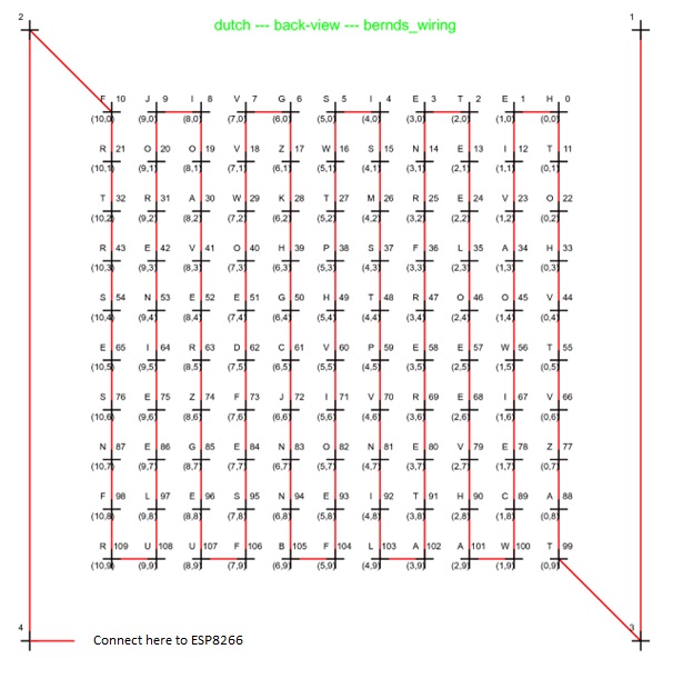
The leds strips, cut in strings of 10 leds, can be connected by led strip connectors and glued to the cut outs in the top and bottom slats (nr. 1 and 11). It could be wise to extend the strip with one length a time and test if leds do light up if you plug the power supply. This enables finding wiring errors. See picture 6 for a wiring diagram.
When all led strips are mounted, cover the back with duct tape. This prevents leakage of light from one character to the other.
Test if your clock works and mount the back plate. See step 6 and 7 in woodwork.
Pictures
- alt:
Picture 1: back of front plate covered with paper
- alt:
Picture 2: matrix of slats
- alt:
Picture 3: numbering of the slats
- alt:
Picture 4: all parts put in place, but no tape applied to the back of all the leds
- alt:
Picture 5: back plate of the wordclock with a cut out for the DC plug, 4 screw holes and a hole for hanging the clock
- alt:
Picture 6: wiring of the led strip, seen from the backside
- alt:
Picture 7: wiring scheme